
CNC Turning for Precision Shaft Production – A Technical Guide for Industrial Buyers
1. Introduction
In the hierarchy of mechanical components, the shaft serves as the fundamental element of power transmission and motion control. From high-speed automotive transmissions to heavy-duty industrial conveyor systems, the reliability of the entire assembly hinges on the geometric integrity of the shaft.
The manufacturing process selected for industrial shaft manufacturing determines the component’s performance characteristics, including rotational balance, vibration levels, and the fatigue life of mating components such as bearings and seals. While shafts can be produced via various methods, CNC turning has established itself as the global standard for primary shaft production.
Historically, manual lathes sufficed for low-volume, low-precision work. However, modern engineering demands tighter tolerances and higher production velocities that manual operations cannot consistently achieve. CNC turning shafts ensures that critical parameters—specifically concentricity and runout—are maintained within micron-level specifications across production runs ranging from dozens to thousands of units. For industrial buyers and engineers, understanding the capabilities and limitations of this process is essential for specifying cost-effective, high-performance components.
2. What Is CNC Turning in Shaft Manufacturing?
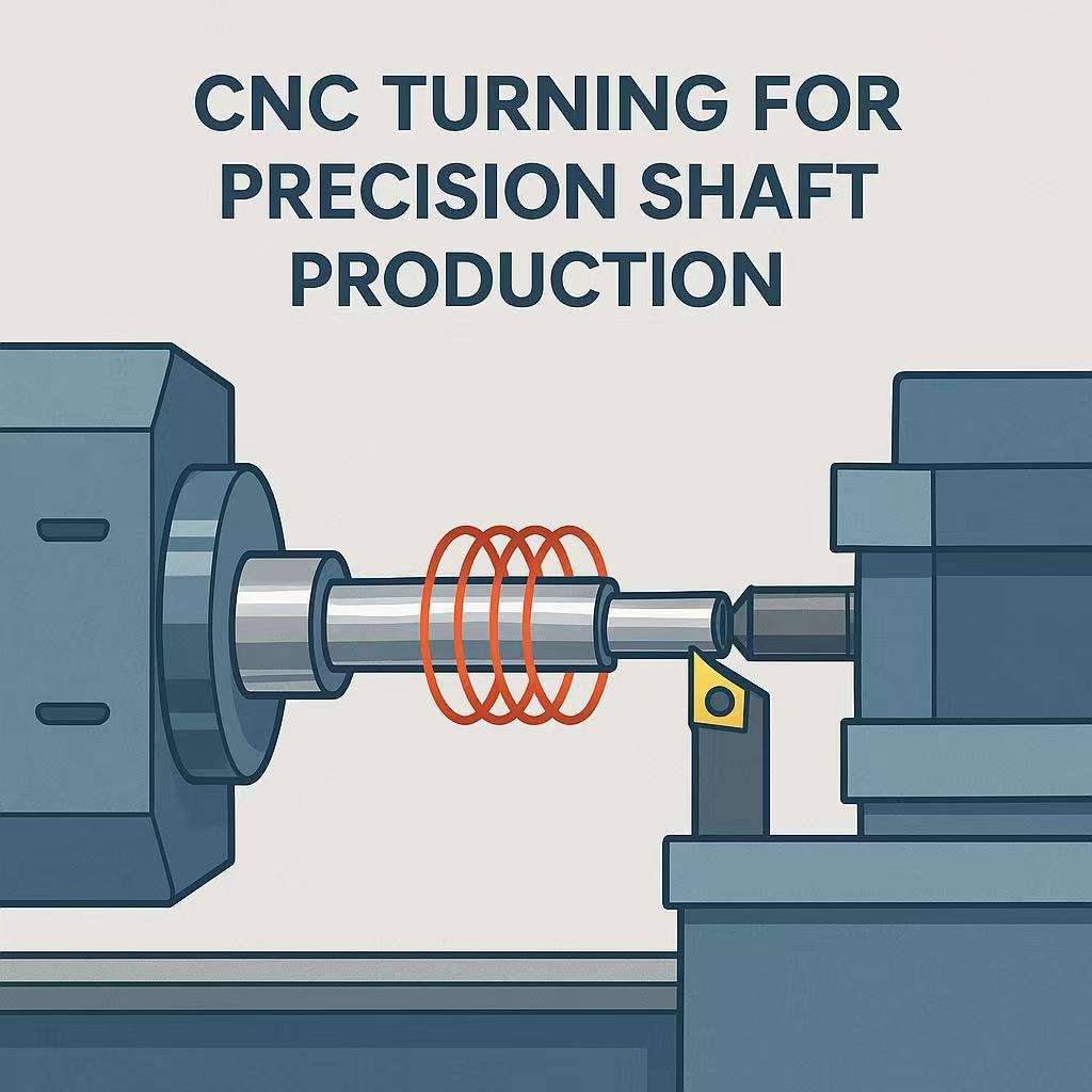
CNC turning is a subtractive manufacturing process used to generate cylindrical parts. Unlike milling, where the cutting tool rotates and the workpiece remains stationary (or moves along axes), turning involves clamping the raw material (bar stock or forging) in a chuck or collet and rotating it at high speeds against a stationary, single-point cutting tool.
For precision shaft machining, this axial symmetry is critical. The CNC (Computer Numerical Control) system directs the cutting tool along multiple axes (typically X and Z) to remove material, generating the shaft’s outer profile.
While multi-tasking machines now combine milling and turning, the primary geometry of a shaft—its journals, steps, and bearing seats—is created through turning operations. This method is mathematically ideal for producing concentric features, as the part is machined relative to its own axis of rotation.
3. Why CNC Turning Is Critical for Precision Shafts
The transition to CNC turned shafts is driven by engineering requirements rather than mere automation. In dynamic applications, geometric deviations translate directly into mechanical failure.
Concentricity and Runout Control
A shaft typically features multiple diameters (steps) that must share a common centerline. If a bearing journal is slightly off-center relative to the main drive axis, it induces runout. At high RPM, this runout creates centrifugal forces that cause vibration, noise, and premature bearing failure. CNC turning centers machine these features in a single setup (or synchronized transfer), ensuring that all diameters are perfectly concentric.
Diameter Repeatability
In CNC lathe shaft production, the machine follows a programmed tool path with closed-loop feedback. This ensures that the diameter of the first shaft matches the thousandth shaft within strict limits, essential for interference fits with couplings or gears.
Stepped Shaft Geometry
Industrial shafts rarely maintain a uniform diameter. They feature shoulders to locate bearings and steps to accommodate gears. CNC turning allows for the continuous machining of these complex profiles without manual repositioning, eliminating the “stack-up” errors common in manual machining.
4. CNC Turning Process for Shafts (Step-by-Step)
Understanding the production workflow helps buyers identify potential bottlenecks and quality risks.
1. Material Selection and Preparation
Production begins with raw material, typically cold-drawn bar stock or near-net-shape forgings. For high-precision applications, the straightness of the raw stock is verified before machining to prevent vibration during the turning process.
2. Rough Turning
The objective here is rapid material removal. Rigid cutting tools remove the bulk of the material to approach the final shape. Roughing releases internal residual stresses in the metal, which can cause the shaft to warp. Experienced manufacturers leave sufficient stock material to correct this distortion during finishing.
3. Semi-Finishing and Finishing
Finish turning is performed with precision inserts and finer feed rates. This pass establishes the final dimensional accuracy and surface finish. For precision shaft machining, thermal expansion must be managed; coolants are used not just for lubrication, but to maintain a stable workpiece temperature.
4. Secondary Operations
While the shaft is still chucked, the CNC machine may perform auxiliary operations such as cutting grooves for snap rings, threading shaft ends, or centering drilling.
5. Tolerances Achievable with CNC Turning
Engineers must distinguish between what is possible and what is economical. While CNC machines are highly precise, relying solely on turning for ultra-precision fits can drive up costs due to tool wear management and cycle times.
Diameter Tolerances
For CNC turning shafts, a standard achievable tolerance is ±0.01 mm to ±0.02 mm (ISO IT7 or IT8). This is generally sufficient for clearance fits and some transition fits. Achieving tolerances tighter than this (e.g., ±0.005 mm) via turning requires specialized environmental controls and tooling, often pushing the process into the realm where grinding is more reliable.
Shaft Tolerances and ISO Fits
h7 / g6 Fits: Common for bearing journals and coupling interfaces. Capable suppliers can achieve these via hard turning, though grinding is often preferred for process capability (Cpk).
Length Tolerances: typically ±0.1 mm, though ±0.05 mm is achievable if critical.
Runout and Cylindricity
Total Indicated Runout (TIR) is often the most critical specification. CNC turning can typically hold runout to within 0.01 mm to 0.03 mm depending on the shaft’s length-to-diameter ratio. Long, slender shafts are prone to deflection under tool pressure, requiring steady rests or follow rests to maintain straightness.
For most industrial shaft applications, CNC turning defines geometry, while grinding is reserved only for functional journals where tolerance capability must exceed turning limits.
6. Surface Finish from CNC Turning
The surface finish, measured in Ra (Roughness Average), dictates how the shaft interacts with seals and lubricants.
Typical Ra Values
Rough Turning: Ra 3.2 µm to 6.3 µm.
Standard Finish Turning: Ra 1.6 µm to 3.2 µm.
Fine Finish Turning: Ra 0.4 µm to 0.8 µm (achievable with wiper inserts and slow feed rates).
Functional Implications
For static surfaces or structural steps, a standard finish is sufficient. However, for dynamic sealing surfaces (lip seals) or bushing interfaces, the surface texture is critical. If the “peaks” of the surface profile are too high, they will abrade the seal. If the turning process cannot achieve the required Ra (typically <0.8 µm for seals), a secondary polishing or grinding operation is required.
7. CNC Turning vs. CNC Grinding for Shafts
While turning creates the geometry, grinding perfects it. Understanding the distinction is vital for cost control.
| Feature | CNC Turning | CNC Cylindrical Grinding |
| Primary Function | Geometry creation, bulk removal | Tolerance refinement, surface finishing |
| Typical Accuracy | ±0.01 mm – ±0.02 mm | ±0.002 mm – ±0.005 mm |
| Surface Finish | Ra 0.8 µm – 3.2 µm | Ra 0.2 µm – 0.8 µm |
| Cost | Lower (faster cycle time) | Higher (slower, requires turning first) |
| Hardened Materials | Hard turning possible (<60 HRC) | Ideal for hardened shafts (>60 HRC) |
For most industrial shaft manufacturing, the optimal workflow is often CNC turning followed by heat treatment, and finally CNC grinding for critical journals only.
8. Shaft Types Best Suited for CNC Turning
Certain shaft geometries are inherently optimized for the CNC turning process.
Stepped Shafts: The most common application. The lathe can easily transition between diameters to create shoulders for locating components.
Threaded Shafts: CNC lathes can perform single-point threading or thread rolling, producing threads that are perfectly concentric with the shaft axis.
Hollow Shafts: Through-spindle coolant and boring bars allow lathes to machine internal diameters for weight reduction or fluid flow.
Spline-Ready Blanks: CNC turning creates the precise major and minor diameters required before the shaft is sent for hobbing or spline cutting.
Limitations
Extremely long, thin shafts (high length-to-diameter ratio) are difficult to turn without inducing chatter or deflection. These often require Swiss-style lathes or specialized support systems.
9. Quality Control in CNC Turned Shaft Production
In shaft manufacturing, quality control focuses heavily on geometry and rotational integrity. Unlike prismatic parts, a shaft’s quality is defined by its behavior while rotating.
Inspection Methods
In-Process Probing: Advanced CNC lathes utilize touch probes to measure part dimensions during the machining cycle, allowing for automatic tool offset adjustments to maintain shaft tolerances.
Laser Micrometers: Non-contact measurement systems used to verify diameters rapidly.
Circular Runout Checks: The shaft is placed on V-blocks or between centers, and a dial indicator measures the variation as the part is rotated. This verifies that the journals are concentric.
Cylindricity and Roundness: For high-precision applications, Coordinate Measuring Machines (CMM) or roundness testers map the shaft profile to ensure it is perfectly round, not lobed.
10. Buyer Considerations When Sourcing CNC Turned Shafts
For procurement managers in the US and Southeast Asia, specifying shafts requires balancing engineering needs with manufacturing reality.
1. Avoid Over-Tolerancing
Do not apply a blanket tolerance (e.g., ±0.005 mm) to the entire shaft. Only apply tight tolerances to bearing seats and seal surfaces. Unnecessary precision on clearance diameters drastically increases cycle time and inspection costs.
2. Material Straightness
For long shafts, specify the required straightness of the raw material or the finished part. Turning cannot always correct bent raw stock; it often results in a shaft that warps after being removed from the chuck.
3. Define Concentricity Requirements
Clearly identify which datums are critical. If a gear must align perfectly with a bearing, the drawing must utilize GD&T to link those two features.
4. Evaluate Supplier Capacity
Ask suppliers about their maximum turning length and diameter. Also, verify their ability to handle secondary operations (like heat treatment or grinding) internally or through an approved network, as this impacts lead time.
11. Conclusion
CNC turning serves as the backbone of modern precision shaft machining. It offers the speed and flexibility required for industrial production while maintaining the geometric control necessary for high-performance machinery. While it is often the first step in a sequence that may include heat treatment and grinding, the accuracy achieved during the turning phase sets the baseline for the shaft’s final quality.
For industrial buyers, success lies in clearly defining critical-to-quality features—specifically concentricity and runout—and selecting manufacturing partners who possess the metrology equipment to verify them. Understanding the true capabilities of CNC turning allows buyers to specify only what is functionally necessary—avoiding unnecessary cost while ensuring mechanical reliability.