
Final Checklist for Ordering Custom CNC Shafts – A Practical Guide for Industrial Buyers
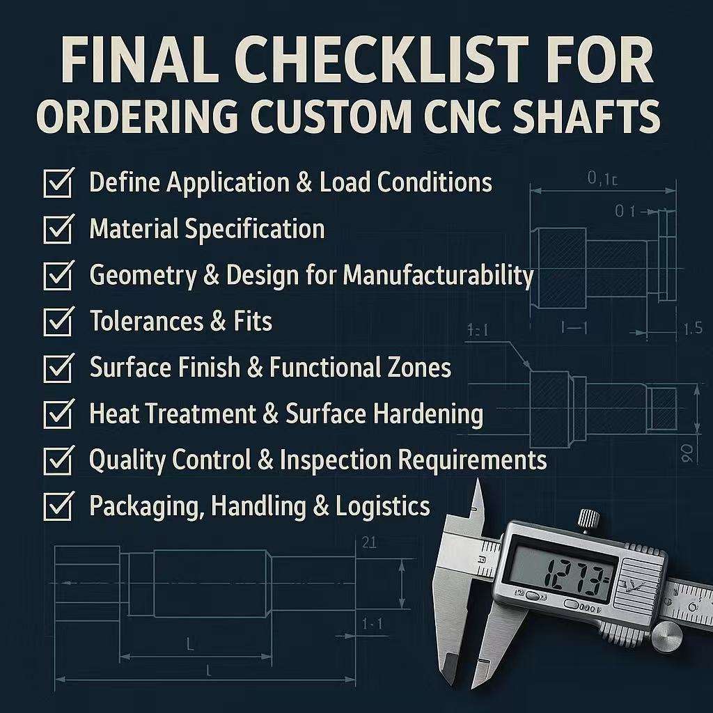
1. Introduction – Why a Checklist Is Essential for Custom CNC Shafts
In the hierarchy of mechanical components, the shaft is often the single point of failure. Whether it is driving a high-speed electric motor, actuating a robotic arm, or transmitting torque in a heavy-duty gearbox, the shaft bears the brunt of the mechanical load. For OEM buyers and sourcing managers, custom CNC shafts represent a unique procurement challenge. They are not off-the-shelf commodities; they are engineered components where a single ambiguity in the drawing or specification can lead to catastrophic field failure.
Common mistakes in the procurement process—such as omitting runout tolerances, specifying vague material grades, or ignoring heat treatment distortion—often result in parts that fit geometrically but fail mechanically. In many industrial applications, a single shaft failure can shut down an entire production line, leading to downtime losses far exceeding the value of the shaft itself.
A robust ordering checklist is not merely administrative paperwork; it is a critical risk-control tool. It ensures that the CNC shaft manufacturing process aligns perfectly with the engineering intent, bridging the gap between the design desk and the machine shop. This guide provides a comprehensive checklist to ensure accuracy, reliability, and manufacturability in your next shaft order.
2. Step 1: Define Application & Load Conditions
Before a supplier can quote accurately or suggest manufacturing optimizations, they must understand the operational context. A shaft designed for a low-speed conveyor has vastly different requirements than one designed for a high-RPM turbine, even if their dimensions are similar.
Contextual Data Checklist:
Load Type: Is the load static or dynamic? Is the shaft subject to high start-up torque, shock loads, or continuous vibration?
Duty Cycle: Will the equipment run intermittently or 24/7? Continuous duty often dictates higher fatigue strength requirements.
Operating Speed (RPM): High speeds require tighter concentricity and dynamic balancing.
Environment: Will the shaft be exposed to abrasive dust, corrosive chemicals, saltwater, or extreme temperatures? This dictates material and coating choices.
Providing this context prevents the industrial shaft supplier from making dangerous assumptions. It allows them to validate whether the specified material and tolerances are appropriate for the intended lifespan of the component.
3. Step 2: Material Specification Checklist
Material selection is the foundation of shaft reliability. Vague descriptions like “Steel” or “Stainless” are the most common cause of quotation variance and performance issues.
Material Checklist:
Exact Grade: Specify the exact standard (e.g., AISI 4140, 42CrMo4, 17-4PH, 303 Stainless).
Form Factor: Explicitly state if the raw material should be Rolled Bar Stock or a Forged Blank. For large diameter or high-load shafts, forgings provide superior grain structure and impact resistance.
Condition: Define the delivery condition (e.g., Annealed, Normalized, or Pre-Hardened/QT).
Traceability: Mandate a Mill Test Report (MTR) or EN 10204 3.1 certificate with every shipment to verify chemical composition and mechanical properties.
Common Mistake: Specifying “Alloy Steel” without a grade allows the supplier to use the cheapest available option, which may lack the necessary fatigue strength.
4. Step 3: Geometry & Design for Manufacturability (DFM)
The geometry of the shaft dictates the machining strategy and cost. A well-defined drawing minimizes “Requests for Information” (RFIs) and production delays.
Geometry Checklist:
Stepped Diameters: Ensure all diameter changes are clearly dimensioned from a single datum line to prevent tolerance stack-up.
Fillet Radii: Clearly specify radii at all shoulders. Sharp corners act as stress risers and are the primary location for fatigue cracks.
Undercuts/Reliefs: Define grinding reliefs where bearings must seat flush against a shoulder.
Features: Ensure keyways, splines, threads, and cross-holes are fully dimensioned with positional tolerances.
By engaging in early DFM discussions, buyers can often identify non-critical features where tolerances can be loosened, significantly reducing the cost of custom CNC shafts without compromising performance.
5. Step 4: Tolerances & Fits (The Most Critical Section)
Tolerance definition is the single most important technical factor separating a functional CNC shaft from a premature failure. Tolerancing determines the fit and function of the shaft. This section requires the highest level of precision in the RFQ.
Tolerance Checklist:
Bearing Journals: Assign specific ISO tolerance classes (e.g., k6, m6, g6) to all bearing seats. Do not rely on general block tolerances (e.g., ±0.1mm) for these critical areas.
Functional vs. Clearance Zones: Apply tight tolerances only to functional areas (bearings, gears, seals). Leave clearance zones with open tolerances to reduce grinding costs.
Geometric Dimensioning and Tolerancing (GD&T):
Runout (TIR): Specify maximum Total Indicated Runout relative to the bearing axis datum.
Straightness: Critical for long, slender shafts.
Cylindricity: Essential for high-precision sliding fits.
Common Mistake: Over-tolerancing the entire shaft length. This forces the manufacturer to grind the entire part, unnecessarily doubling the cost.
6. Step 5: Surface Finish & Functional Zones
Surface roughness (Ra) directly impacts seal life and bearing performance. A shaft that is too rough will destroy seals; a shaft that is too smooth may fail to retain lubrication.
Surface Finish Checklist:
Bearing Seats: Typically Ra 0.4 – 0.8 µm (Ground finish).
Seal Journals: Typically Ra 0.2 – 0.4 µm.
Lead-Free Requirement: For rotary seals, explicitly state “Plunge Grind / No Lead.” Helical grinding marks can act as a screw pump, drawing oil out of the seal interface.
Non-Functional Areas: Allow Ra 1.6 – 3.2 µm (As-turned finish) to save costs.
Coating Impact: If the shaft is plated (chrome, nickel, DLC), specify if dimensions and roughness apply before or after coating.
7. Step 6: Heat Treatment & Surface Hardening
Heat treatment imparts the necessary hardness to resist wear and the strength to resist torque. However, it also introduces distortion.
Heat Treatment Checklist:
Method: Specify the process (Quench & Temper, Induction Hardening, Nitriding, or Carburizing).
Hardness Range: Define the required hardness in Rockwell C (e.g., HRC 50-55).
Depth: For induction hardening or carburizing, specify the effective case depth (e.g., 1.5mm – 2.0mm).
Stress Relief: For long shafts, require a stress relief cycle after rough machining to minimize warping.
Crucial Warning: Heat treatment causes metal to move. Ensure the supplier plans for post-heat-treat grinding to restore straightness and dimensional accuracy.
8. Step 7: Quality Control & Inspection Requirements
You get what you inspect, not what you expect. Define the acceptance criteria clearly.
Inspection Checklist:
Dimensional Report: Required for critical dimensions on a sample basis (e.g., AQL 1.0) or 100% for critical journals.
Runout Verification: Require TIR measurements taken between centers or on V-blocks.
Surface Roughness: Verification with a profilometer for seal areas.
Hardness Testing: Verification of HRC values.
NDT (Non-Destructive Testing): For high-load shafts, specify Ultrasonic Testing (UT) or Magnetic Particle Inspection (MPI) to detect internal or surface cracks.
First Article Inspection (FAI): Mandatory for new part numbers to validate the process before volume production.
Visual inspection alone is insufficient for precision CNC shafts. Buyers must demand data.
9. Step 8: Packaging, Handling & Logistics
A precision-ground shaft is fragile. Impact damage during transit is a leading cause of rejection.
Packaging Checklist:
Individual Protection: Plastic netting or heavy paper sleeves for every shaft to prevent metal-on-metal contact.
Rust Prevention: Application of rust-preventative oil and VCI (Volatile Corrosion Inhibitor) paper/bags, especially for sea freight.
Crating: Wooden crates (ISPM 15 compliant) with dividers for heavy shafts.
Orientation: Instructions to store/ship long shafts flat and fully supported to prevent bowing.
10. Step 9: RFQ & Supplier Communication Checklist
To streamline the quotation process and reduce back-and-forth communication, ensure your Request for Quotation (RFQ) package is complete.
Final RFQ Checklist:
[ ] Application Context: Brief description of load and environment.
[ ] Complete Drawings: PDF with GD&T + STEP/IGES 3D model.
[ ] Material Specs: Grade, Form, and Condition.
[ ] Heat Treatment: Method, Hardness, and Depth.
[ ] Critical Tolerances: Clearly highlighted fits and runout.
[ ] Inspection Requirements: defined (FAI, PPAP, MTR).
[ ] Packaging: Rust and impact protection specified.
[ ] Volume: Batch sizes and Estimated Annual Usage (EAU).
Providing this level of detail signals to the CNC shaft manufacturing partner that you are a serious buyer who understands the process, often resulting in more accurate and competitive pricing.
11. Conclusion – Ordering Custom CNC Shafts Is Risk Management
Sourcing custom CNC shafts is fundamentally an exercise in risk management. The difference between a reliable, long-lasting component and a field failure often lies in the details of the specification. By rigorously defining materials, tolerances, heat treatment, and inspection protocols, buyers transform the procurement process from a simple transaction into an engineering partnership.
Using this checklist ensures that nothing is left to interpretation. It empowers procurement managers to hold suppliers accountable and ensures that the final product meets the stringent demands of modern industrial applications. Treat your supplier as an extension of your engineering team, provide them with clear, comprehensive data, and the result will be a supply chain characterized by consistency, quality, and reduced total cost of ownership. For buyers new to shaft sourcing, this checklist should be used together with a complete understanding of supplier manufacturing capabilities.