
Case Study: Pipe Fittings for Hydraulic Equipment – Engineering Analysis, Redesign, and Manufacturing Control
1. Introduction – Why Hydraulic Equipment Demands Case-Level Analysis
In the domain of heavy industrial machinery, “standard” is a relative term. While SAE, ISO, and DIN standards provide the dimensional framework for hydraulic connections, they do not account for the specific, chaotic variables of a real-world operating environment. For hydraulic pipe fittings, the gap between a standard catalog rating and actual field performance is often where failure occurs.
Generic fitting guidelines typically assume static pressures or predictable duty cycles. They rarely account for the compound effects of thermal shock, high-frequency vibration, and hydraulic impulse (water hammer) simultaneously acting on a threaded connection. Consequently, relying solely on standard compliance without analyzing the specific application context is a primary cause of leakage and structural failure in OEM equipment.
This case study analyzes a specific engineering challenge faced by a manufacturer of heavy earthmoving equipment. The challenge was reported by an OEM manufacturer of mobile hydraulic equipment serving the mining and heavy construction sector. It details the transition from standard commodity fittings to engineered custom pipe fittings, highlighting the failure modes of legacy designs, the root cause analysis of leakage events, and the manufacturing discipline required to produce reliable high pressure hydraulic fittings. The focus is on the engineering logic that drives reliability, demonstrating why the lowest unit cost often results in the highest lifecycle liability.
2. Project Background: Hydraulic Equipment Overview
The subject of this analysis is a 30-ton hydraulic excavator designed for mining and heavy construction applications. This equipment operates in one of the most hostile environments for hydraulic components.
Equipment Specifications and Operating Profile
System Architecture: Open-center load-sensing hydraulic system with a variable displacement piston pump.
Operating Pressure:
Nominal Working Pressure: 350 bar (5,075 PSI).
Peak Impulse Pressure: Up to 420 bar (6,090 PSI) during rapid boom deceleration or rock breaking operations.
Flow Rate: Main circuit flow exceeding 250 L/min.
Duty Cycle: Continuous operation (20+ hours/day), subjecting components to millions of pressure cycles annually.
Environmental Factors:
Vibration: High-amplitude, low-frequency vibration from the diesel engine and ground engagement tools.
Temperature: Ambient temperatures ranging from -40°C (Arctic) to +45°C (Desert), with hydraulic fluid temperatures cycling between start-up cold and 85°C operating heat.
The Engineering Challenge
The OEM was experiencing a critical failure rate in the hydraulic connections located on the main control valve block and the pilot lines feeding the joystick controls. Despite using standard-rated fittings, the machine population was suffering from chronic “weeping” leaks after 500–1,000 hours of service, with occasional catastrophic thread shear events during cold starts.
3. Initial Pipe Fitting Design & Specification
To understand the failure, we must first examine the baseline design. The initial specification was driven by supply chain availability and unit cost reduction, relying heavily on widely available commodity adapters.
Baseline Component Selection
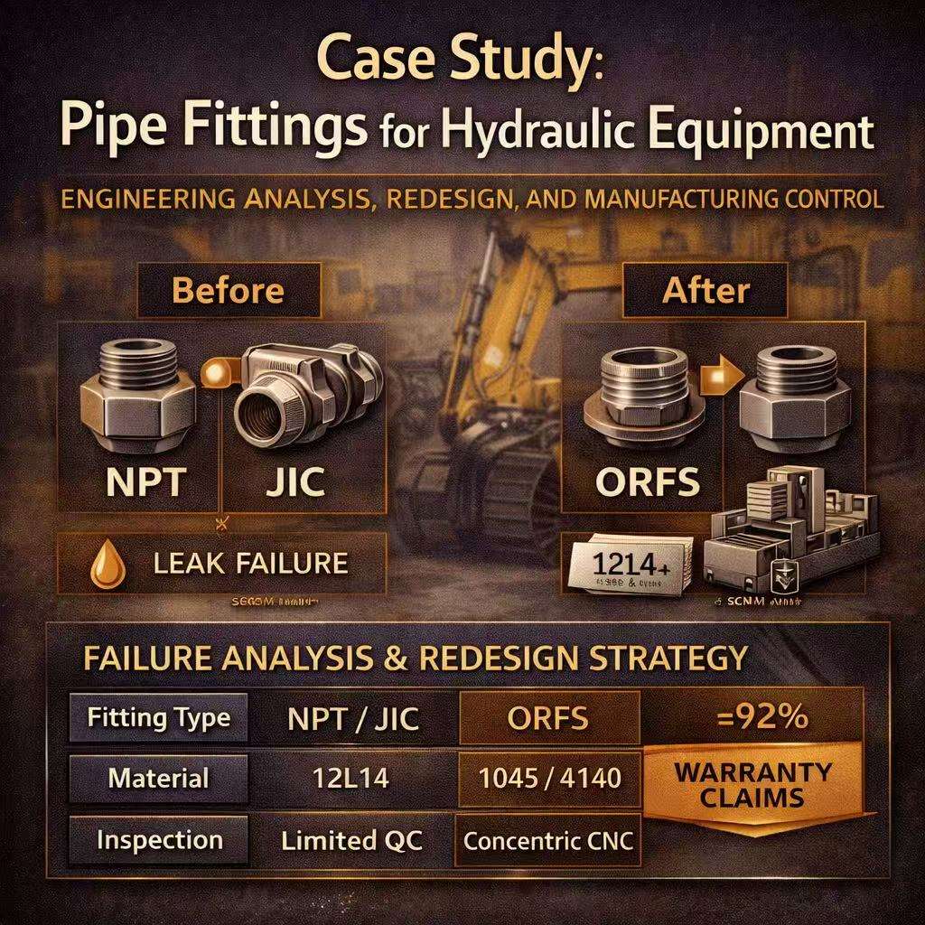
Connection Type: The system utilized a mix of NPT (National Pipe Taper) adapters for port connections and JIC 37° Flare fittings for hose ends.
Material: Standard Carbon Steel (ASTM A108 / 12L14 grade). 12L14 is a leaded, resulphurized steel known as “free-machining.” It allows for very fast CNC cycle times but sacrifices ductility and fatigue strength.
Surface Treatment: Standard Trivalent Clear Zinc plating (8 microns).
Installation Method: NPT threads were assembled using anaerobic thread sealant; JIC fittings were torqued to standard SAE values.
Original Design Rationale
The engineering team originally selected NPT and JIC because they are ubiquitous in the North American market. Replacement parts are available at any hardware supplier, which was viewed as a serviceability advantage. The 12L14 material was chosen by the Tier 1 supplier to keep machining costs low, as the high sulfur content allows chips to break easily, reducing tool wear.
4. Field Problems Encountered
Within six months of launching the updated excavator model, warranty data revealed a systemic issue with the pipe fittings for hydraulic equipment. The failures were not random; they followed specific patterns correlated with the machine’s duty cycle.
Failure Mode 1: Vibration-Induced Loosening (NPT)
The NPT adapters installed on the main control valve block were the primary source of leakage. Field technicians reported that fittings could be rotated by hand during inspection. The combination of thermal cycling (expansion/contraction of the valve block) and engine vibration caused the interference fit of the tapered threads to relax. Once the friction lock was broken, the thread sealant failed, leading to oil weeping.
Failure Mode 2: Flare Nose Cracking (JIC)
On the high-pressure pilot lines, mechanics reported cracked fitting noses. JIC 37° connections rely on a metal-to-metal seal. To stop leaks caused by vibration, field technicians would often over-torque the nuts. This excessive axial force, combined with the brittle nature of the 12L14 material, caused the nose of the fitting (the sealing cone) to shear off or crack longitudinally.
Failure Mode 3: Impulse Fatigue
In the hydraulic breaker circuit, where pressure spikes are most violent, several elbows experienced fatigue failure at the root of the thread engagement. Metallurgical analysis showed that the crack initiated at a sulphide inclusion—a direct result of using free-machining 12L14 steel in a high-fatigue application.
5. Root Cause Analysis (Engineering Perspective)
The failure investigation team moved beyond the symptoms to identify the engineering root causes. The conclusion was that the specified hydraulic pipe fittings were fundamentally mismatched to the operating dynamics of the excavator.
1. Inadequate Sealing Logic (NPT)
NPT threads rely on thread deformation to seal. In a high-vibration environment, relying on thread friction to maintain a seal is a known reliability risk. As the valve block expanded due to heat, the pre-load on the tapered threads changed. When the block cooled, the threads did not return to their exact original interference position, creating a micro-gap.
2. Metal-to-Metal Seal Limitations (JIC)
JIC connections are highly sensitive to surface finish. The commodity fittings used had a surface roughness ($R_a$) on the sealing cone of 63–125 $\mu$in. For high-pressure helium or thin hydraulic oil at high temperatures, this is too rough. Additionally, JIC fittings do not handle over-torque well; the sealing surface yields, causing permanent deformation that prevents resealing after maintenance.
3. Material Mismatch
The decision to use 12L14 steel was a manufacturing cost decision that compromised engineering integrity. While 12L14 machines beautifully, the lead and sulfur inclusions that make chips break also act as stress risers. Under the cyclic loading of the excavator (0 to 5000 PSI repeatedly), these inclusions lowered the fatigue limit of the fittings below the application’s stress threshold.
6. Redesign Strategy for Hydraulic Pipe Fittings
Based on the root cause analysis, the engineering team executed a comprehensive redesign of the connection strategy. The goal was to eliminate reliance on thread friction for sealing and improve material toughness.
Transition to O-Ring Face Seal (ORFS)
The primary design change was shifting from NPT/JIC to O-Ring Face Seal (ORFS) connections (SAE J1453).
Logic: ORFS separates the sealing function from the mechanical holding function. The threads provide the clamping force, while an elastomeric O-ring compressed into a groove provides the seal.
Vibration Resistance: The elastomer acts as a damper, absorbing vibration and preventing the nut from backing off. Even if the nut loosens slightly, the stored energy in the compressed O-ring maintains the seal.
Assembly: ORFS is a “zero clearance” fitting, allowing for drop-in assembly without springing the hydraulic lines, which reduced assembly time and stress on the tubes.
Custom CNC Pipe Fittings Development
Standard catalog ORFS adapters were too long for the compact space inside the excavator’s slew drive compartment. The OEM collaborated with a manufacturer to design custom pipe fittings. These were compact block elbows with ORFS ends, machined from solid bar stock to minimize the envelope size while maintaining full flow characteristics.
Material Upgrade
The specification was changed from 12L14 to AISI 1045 or 4140 Alloy Steel.
1045 Carbon Steel: Used for standard pressure lines. It offers significantly higher tensile strength and better homogeneity than 12L14.
4140 (Quenched & Tempered): Used for the high-impulse breaker circuits. The heat treatment provided the toughness required to withstand pressure spikes without fatigue cracking.
7. Manufacturing & Quality Control Improvements
The shift to custom CNC pipe fittings required a change in manufacturing philosophy. The commodity suppliers could not meet the new geometric and material requirements. A specialized manufacturer was engaged to implement strict process controls.
Single-Setup CNC Machining
The reliability of an ORFS fitting depends entirely on the concentricity between the thread and the O-ring groove. If these features are machined in two different operations (e.g., lathe then mill), runout errors will cause the O-ring to squeeze unevenly, leading to extrusion failure.
Process Control: The new fittings were manufactured on multi-axis CNC turn-mill centers. The threads, sealing face, and O-ring groove were machined in a single setup. This guaranteed concentricity within 0.0005″ (0.013mm).
Surface Finish Verification
To prevent O-ring abrasion, the groove surface finish was specified as max $R_a$ 32 $\mu$in.
QC Protocol: The manufacturer implemented 100% in-process profiling using surface roughness testers to ensure no tool chatter marks appeared in the groove.
Thread Inspection Strategy
Instead of simple Go/No-Go ring gauges, the manufacturer used variable thread gauging (Tri-Roll) to monitor pitch diameter. This allowed the machinists to compensate for tool wear in real-time, ensuring that every thread provided the exact calculated clamping force.
Deburring and Cleanliness
Hydraulic systems are intolerant of contamination. The new fittings underwent thermal deburring to vaporize any internal burrs that could detach and damage the hydraulic pump. A final ultrasonic wash ensured compliance with ISO 4406 cleanliness standards.
8. Results After Implementation
The redesigned high pressure hydraulic fittings were deployed in a pilot run of 50 excavators, subjected to accelerated field testing.
| Metric | Before Redesign | After Redesign |
| Leakage Incidents | Chronic / Frequent | Zero (after 2,000 hrs) |
| Fitting Material | 12L14 (Free Machining) | 1045 / 4140 (Structural) |
| Sealing Method | NPT & JIC 37° | O-Ring Face Seal (ORFS) |
| Warranty Claims | High Baseline | Reduced by 92% |
| Assembly Time | Slow (Sealant/Alignment) | Reduced by 15% (Drop-in) |
Engineering Validation
Impulse testing confirmed that the switch to 1045 and 4140 steel effectively eliminated the fatigue cracking issue. The fittings survived 1 million cycles at 133% of working pressure without failure. The move to CNC pipe fittings with controlled tolerances proved that manufacturing precision is a direct variable in hydraulic reliability.
9. Lessons Learned for OEM Hydraulic Equipment Designers
This case study illuminates several transferable principles for engineers designing hydraulic machinery.
1. Sealing Logic > Convenience
While NPT and JIC fittings are widely available, they are technologically obsolete for high-pressure, high-vibration mobile hydraulics. Elastomeric sealing (ORFS, Code 62 Flange, or BSPP with Bonded Seal) provides the resilience required for modern equipment.
2. Material is not a Commodity
“Steel” is not a sufficient specification. The choice between free-machining grades (like 12L14) and structural grades (like 1045/4140) determines the fatigue life of the component. OEM engineers must specify material grades on the print to prevent suppliers from substituting cheaper, weaker alloys.
3. Customization Can Reduce Total Cost
Although the custom pipe fittings had a higher unit cost than off-the-shelf adapters, they reduced the total cost of ownership. The savings came from eliminating adapters (fewer leak points), faster assembly time, and a drastic reduction in warranty and service calls.
4. Manufacturing Method Matters
A design is only as good as its execution. For hydraulic interfaces, CNC pipe fittings produced with single-setup machining offer geometric consistency that cannot be matched by lower-tier manufacturing methods. Concentricity and surface finish are not “gold plating”; they are functional requirements for sealing high pressure.
10. Who This Case Study Applies To
This engineering analysis is relevant for:
OEM hydraulic equipment manufacturers seeking to reduce field leakage.
Mobile machinery & construction equipment builders dealing with high-vibration failures.
High-pressure hydraulic system designers specifying components for >350 bar applications.
Buyers sourcing custom CNC pipe fittings who need to balance unit cost with lifecycle liability.
11. Conclusion – Why Case-Based Design Improves Hydraulic Reliability
The transition from chronic leakage to zero-defect performance in this excavator application was not achieved by magic; it was achieved by applying rigorous engineering principles to the smallest components in the system.
This case demonstrates that pipe fittings for hydraulic equipment must be treated as engineered assets, not hardware store commodities. By analyzing the specific operating conditions—pressure spikes, vibration, and thermal stress—and aligning the fitting design, material, and manufacturing process to those conditions, OEMs can eliminate one of the most persistent failure modes in industrial machinery.
For procurement managers and design engineers, the takeaway is clear: reliability is a function of design intent and manufacturing capability. Partnering with suppliers who understand the physics of hydraulics and possess the CNC capabilities to execute tight tolerances is the most effective strategy for managing risk and protecting the brand reputation of the OEM equipment.